My $15,000 Lesson
My first contractor installed a 12V inverter for a full house. Batteries melted. Toxic fumes.
Had to evacuate during a hurricane. That disaster sent me to the US Solar Institute.
 TARIFF ALERT: Solar prices rising 25-40% in 2025 - Secure American-made independence NOW
Inverter troubleshooting made simple. Do not panic. Most problems are fixable in 15 minutes.
Built for the homeowner staring at a blinking red light at 2 AM.
Last Updated: February 2026 | US Solar Institute Trained | 13+ Years Off-Grid
80% of inverter errors come from 5 causes: blocked vents, loose connections, low battery voltage, overloading, or corroded terminals.
None of those require a technician. A multimeter and a screwdriver fix most of them.
Try all 6 fixes below before spending $200-$800 on a service call.
Wondering if your inverter is undersized? Find out in 60 seconds.
Use the Free Calculator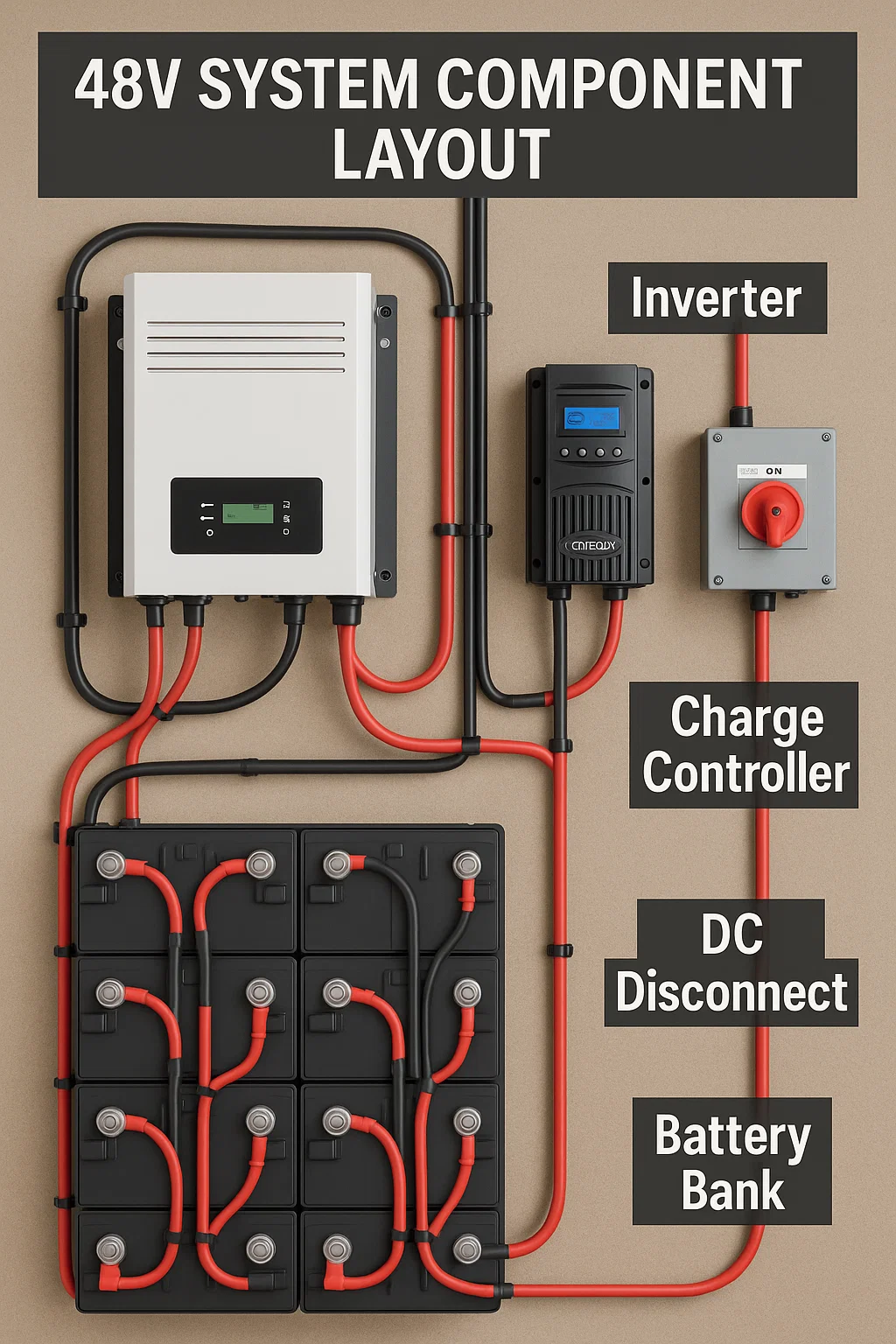
Your inverter is not broken. It is talking to you. Inverter troubleshooting starts with reading the code.
Here is what the most common codes actually mean:
| Code | Meaning | Cause | Fix |
|---|---|---|---|
E01/OVP | Over Voltage | Battery voltage too high | Check charge controller settings |
E02/UVP | Under Voltage | Battery voltage too low | Charge batteries or reduce load |
E03/OCP | Over Current | Drawing too much power | Disconnect high-draw appliances |
E04/OTP | Over Temperature | Inverter overheating | Improve ventilation, clean fans |
E05/SHORT | Short Circuit | Output short detected | Check all AC connections |
E06/OLP | Overload | Continuous overload | Reduce connected load |
Key inverter troubleshooting fact: 80% of these codes come from environmental factors. Not equipment failure.
Dust blocking vents. Loose battery connections. Too many appliances plugged in at once. Corroded terminals creating resistance.
Technicians know this. They still charge $300 to "diagnose" it.
Have you ever paid someone to tighten a loose wire?
Turn off inverter. Disconnect AC loads. Disconnect DC input. Wait 5 minutes for capacitors to discharge.
Test with a multimeter before touching anything. Inverter troubleshooting rule one: verify zero voltage first.
This inverter troubleshooting fix solves more problems than any other. Dust, spider webs, stored boxes against the unit.
Clear all vents. Test cooling fans. Ensure 6 inches minimum clearance on every side. 12 inches on top.
Loose connections create resistance. Resistance creates heat. Heat melts terminals. Melted terminals destroy inverters.
Check DC input terminals. Check AC output terminals. Look for discoloration or corrosion. Apply dielectric grease after tightening.
Measure voltage at battery terminals under load. Then measure at inverter DC input under the same load.
More than 0.5V difference? That is a wiring problem. Not an inverter problem. Check cable size and connections.
Never run an inverter above 80% capacity continuously. Heat generation increases exponentially above that threshold.
Disconnect everything. Start with 100W. Add devices one at a time. Find the trigger point.
Baking soda and water removes corrosion. Dry completely. Apply dielectric grease. Retighten to manufacturer torque specs.
Corroded terminals cause phantom voltage drops. Your Kill-A-Watt meter shows normal. But the inverter sees something different.
Write down the error code. Photograph all connections.
Then power cycle: DC off, wait 60 seconds, DC on, inverter on.
If the code returns after all 5 fixes, you now have documentation for a professional.
I have replaced more inverters from heat damage than anything else. Hot attics. Enclosed cabinets. No ventilation.
Same story every time. If you are uncomfortable in the space, your inverter is too.
An undersized inverter throws codes constantly. Our calculator tells you in 60 seconds.
Use the Free CalculatorMost inverter troubleshooting problems trace back to installation day. Bad location. No ventilation plan. Wrong clearances.
Here is what kills inverters before their time:
Attics exceed 140°F in summer. Garages without ventilation trap heat. Basements without dehumidifiers breed corrosion.
Maximum ambient temp: 104°F. Optimal: below 77°F. Every 18°F increase halves component life.
The National Fire Protection Association publishes clearance requirements.
A 3000W inverter generates 150-300W of heat at full load. That heat must go somewhere.
Rule: 1 square foot of vent area per 1000W capacity. Low inlet near floor. High outlet near ceiling.
Cross ventilation is best. Inlet and outlet on opposite walls.
12V systems draw massive current for household loads. Wires overheat. Batteries strain. Efficiency tanks.
48V is the standard for any system powering a full home. Our Inverter Sizing Guide explains the math.
12 inches top. 6 inches sides. 36 inches front working space. 12 inches from any combustible material.
These are not suggestions. They are NEC code requirements.
Violate them and you void your warranty. Fail inspections. Create fire hazards.
My first contractor installed a 12V inverter for a full house. Batteries melted. Toxic fumes.
Had to evacuate during a hurricane. That disaster sent me to the US Solar Institute.
Climate-controlled utility room. Insulated garage with cross ventilation. Dry basement with dehumidifier. Covered outdoor area with excellent airflow.
Inverter troubleshooting has a safety line. Some fixes are safe for any competent homeowner. Others can kill you.
Error code diagnostics. Cleaning vents and connections. Replacing external fuses. Cooling fan replacement. Cable upgrades. Load management.
Basic tools needed: Klein Tools electrician's kit and a quality multimeter cover most jobs.
Internal component repair. Visible burn damage. Firmware updates. Any work requiring code inspection.
If you smell burning electronics, stop. If you see scorch marks, stop. If you are not 100% confident, stop.
48V DC kills in wet conditions. 120/240V AC is always dangerous. Capacitors hold lethal charge for hours after shutdown.
Wear insulated gloves rated 1000V minimum. Safety glasses. Non-conductive shoes. Keep a Class C fire extinguisher within reach.
Ask: "Do you have experience with my specific brand?" Ask: "What diagnostic equipment do you bring?"
Red flag: suggests replacement without testing. Red flag: quotes over the phone without seeing the system.
Red flag: pressures you to upgrade. Walk away from all three.
A good technician diagnoses first. A bad one sells first.
This inverter troubleshooting routine has prevented 90% of failures I have seen in the field. 15 minutes a month.
Vents clear of dust, debris, spider webs. Display showing normal voltage and load.
No corrosion or discoloration on terminals. No unusual smells. No burn marks anywhere.
6+ inches clearance maintained on all sides. No items stored against the unit.
Hand test: warm is normal. Hot means something changed. Listen for unusual clicking or buzzing.
Record input voltage under various loads. Note any error codes, even brief ones.
Track temperature patterns during peak use. Compare to last month. Look for trends.
Keep this log. It catches problems early.
A slow voltage drop over 3 months reveals a dying connection before it catches fire.
Summer: add ventilation fans if ambient temps rise. Winter: check for condensation on cold mornings.
Spring: clear pollen from vents. Fall: check for rodent nests. Mice love warm inverter cabinets.
Our Seasonal Maintenance Guide covers weather preparation in detail.
15 minutes a month prevents a $3,000 replacement. That math works even if you hate maintenance.
Set a calendar reminder. Your future self will thank you.
Questions about your specific setup? Our OffGridPowerHub GPT gives personalized guidance for your ZIP code.
E01 is over voltage. E02 is under voltage.
E03 is over current. E04 is overheating.
E05 is short circuit. E06 is overload.
Most are caused by environmental factors.
Maximum: 104°F. Optimal: below 77°F.
Every 18°F increase halves component lifespan.
If the room feels hot to you, it is too hot for your inverter.
Minimum 1 sq ft vent area per 1000W capacity.
Low inlet near floor. High outlet near ceiling.
A 3000W inverter generates 150-300W of heat.
Most error codes are safe DIY fixes.
Cleaning vents, tightening connections, reducing load.
Call a pro for internal repairs or visible burn damage.
Usually overheating, low battery voltage, or overloading.
Loose DC connections also cause repeated shutdowns.
The 6 inverter troubleshooting fixes in this guide resolve most cases.
Master inverter troubleshooting by going deeper on related topics:
Top inverter picks tested on real off-grid properties.
Series vs parallel. The wiring that feeds your inverter.
Complete grounding requirements. Code compliance guide.
For the full maintenance framework, visit our Maintenance & Troubleshooting Guide (Pillar 5 hub).
We only recommend products we personally use. Our Victron MultiPlus inverter is what runs our property.
Disclosure: Some links are affiliate links. We earn a small commission at no extra cost to you.
Inverter troubleshooting gets easier with the right foundation. Get the checklist so you know what to look for.
Get the Free Buyer's Checklist